Research
Past research themes
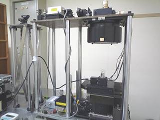
Development of a New Laser Microscope with a Very Wide Field of View
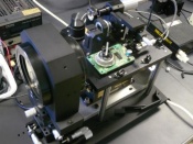
In general, when you observe something small with an optical microscope, a field of view will be getting smaller as the higher magnitude of object lens is used. However, in recent year a processing pattern will be becoming finer and finer. When you inspect such a finer processing pattern, you cannot observe whole interest area at a time with the small field of view of the optical microscope. To do this you must acquire the many images of the interest surface with the interest object moved accurately by mechanical stages and must unit these images. How long does it take to carry out such an observation? You must spend and waste much time over such measurement. So we have been developing the new type of confocal laser microscope that can observe the wider field of view than ever, by using a laser scanning fθ lens incorporated into a housing by a shrink fitter technique. The shrink fit technique has achieved high resolution and a wide field of view simultaneously, because the fθ lens can keep the laser spot diameter less than 3 μm over a whole scanning width of 10mm. Furthermore, the laser microscope developed here can measure an object surface in three dimensions because this microscope is a confocal type. This laser microscope has an observation area of 10mm in width and 8mm in height at a time and the resolving power of line and space is around 1 μm. In addition, the resolving power in the optical axis direction is as small as several μm.
Challenge to wider field of view of 50 mm
In this year, we are trying to make the field of view wide: 10mm at present to 50 mm. To do this new the optical lenses were designed with an optical design soft ware, code V. In addition, for improvement of the resolving power in the optical axis direction and the image acquired, a method of removing the noises was examined from both sides of hardware and software.
Study of a Measuring Method for Strain with the Wide Field of View Laser Microscope
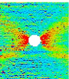
At present a typical sensor used in measuring strain is a strain gauge. Since the strain gauge is small and light, it can measure strain without disturbing the stress state of the body on which the strain gages are glued, and there is a good point that data handling is easy because measured values are easily transformed into electrical signals. But there are bad points that preparations for the strain gage measurement take a time, and it can only do local strain measurement. Therefore, in this study, we search whether we can establish the new strain measurement using the wide field of view laser or not. This new type of laser microscope can measure the surface images with non-contact and over a large area. Furthermore, we try making the distribution map of the strain over a quite large area, 10mm by 8 mm, from two images of before and after deformation.
Observation of the Leakage Flow Paths on Metal Gasket Surface using Laser Microscope with Wide Field of View
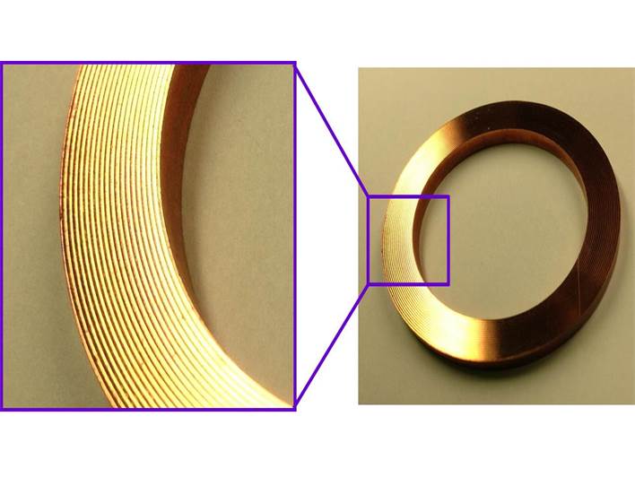
To clarify the sealing characteristics of metal gasket seals, the observation of the real contact area on seal surfaces is very important. In a previous work, to determine the leakage flow paths between the gasket and the flanges, the real contact situation between them was observed using a thin polymer film 1 μm in thickness. In this research, we use a laser microscope with wide field of view recently developed in our laboratory.
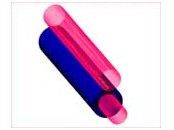
Research of the Paper feeding Mechanism by the Laser Microscope with Very Wide Field of View
Generally, FEM model analysis is used for research the paper feeing mechanism as computer simulation. However, real contact area and microscopic slips between a roller and a paper are not considered in FEM model analysis. In this research, the paper-feeding platen-rubber roller pressed against a optical glass is observed with of 3D laser imager having wide field of view and high resolution for examination of real contact conditions. Deformation between the platen roller and the paper surface is also examined with some torque given to the platen roller as paper feed model. Our objective is to investigate mechanism in paper feed, by observing the condition of real contact between the roller and the glass plate microscopically.
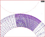
Frictional Properties of Pickup Roller by Laser Microscope with Wide Field of View
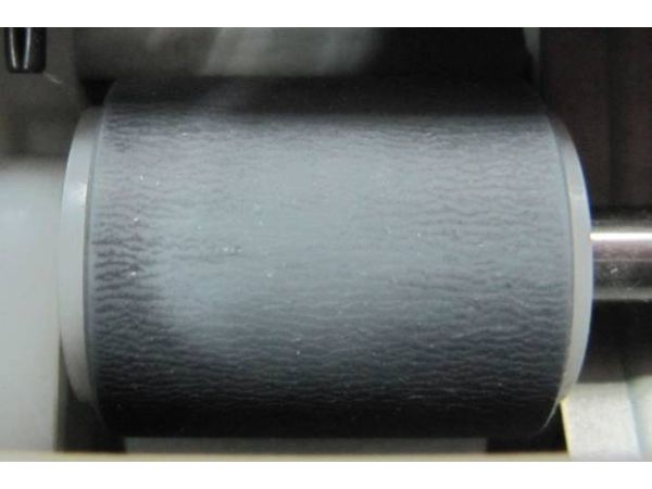
In a paper feeding system, a contact condition analysis between a pickup roller and a printing paper is needed for a stable feeding operation. Direct observation of the apparent contact area is necessary for better understanding of the contact condition. However a contact microscope technique takes a lot of time. Thus another efficient technique is demanded for observation of contact area. In this study, it has been confirmed that observation of the all apparent contact area between the pickup roller and a glass plate is possible by using the laser microscope with wide field of view.
Research of the Dye-sublimation Printer
Effect of real contact area on the optical density of the dye sublimation printer
Dye sublimation is the process used to print smooth, continuous-tone images on printing papers that look truly photographic. This process uses a dye-based ribbon. During printing, a thermal print head containing hundreds of tiny thermal elements pushes and heats the dyes on the ribbon, so that the dyes can be transferred to the printing paper at desired positions. The contact pressure plays an important role in the dye sublimation printer. A lower load applied to the thermal print head is required for a further power saving. However, image quality printed on the printing paper didn't look fine when the applied load was reduced. Then, the contact pressures around the thermal print head were simulated by finite element method, FEM when the lower loads were applied. In addition, the relationships between the contact pressure and the optical density were experimentally obtained for some different combinations of the inks and the papers. The dyes on the ribbon were thought to be transferred and diffused to the paper at real contact area. Thus real contact area of some different types of papers against an optical prism was measured by a contact microscope. At present, the relation between the optical density and real contact area is examined.
Analysis of Contact on Thermal Print Head
The dye sublimation method is to push and heat a dye-based ribbon by thermal print head, and diffuse the dye to the receiving layer on a printing paper. It is important to understanding correlation between printing quality and contact pressure .The dyes is diffused effectively by thermal print head if heater is attached to the higher normal load range. But it is not known to distribution of contact pressure and effect of printing quality that is changed by contact pressure.
The purpose of this study is finding mounting location of thermal print head where is decided by if the dye was diffused under the high pressure of thermal head or not Thus, the distribution of contact pressure is calculated by finite element method, FEM and the contact area is clarified by experiment. The mounting location of thermal print head is decided by result of analysis and experiment.
Analysis of uneven print density
The printing method of dye sublimation printer is to push and heat a dye-based ribbon by a thermal print head, and diffuse the dyes into receiving layer of a printing paper. In a previous work, a real contact area between the ink dyes and the paper was necessary to increase the optical density. At lower load, the image quality of printed on the printing paper became worse because a real contact area was small.
Generally, the image quality on the printed paper was evaluated by human beings, evaluation results vary by person. It is very difficult to evaluate quantitatively. In this study, fractal dimension which considers human vision characteristic, human evaluation and optical density were applied to evaluate the image quality.
Research of 3D Precision Laser Processing Equipment with Wide Processing area
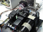
Generally in laser processing machines mechanical stages or robot arms are used to irradiate a laser beam to a desired position. Such positioning systems have wide process area and great positioning accuracy. However its processing speed is very slow. We have developed a fine laser processing equipment with high accuracy positioning as well as wide process area. Galvanometer scanners and f lens using the shrink fitter technique have made it possible to move the laser spots faster than the mechanical stages do. In the scanning lens unit decentering of each lens has a bad influence on positioning accuracy of the laser spot. We have used our own technology, Shrink fitter, which is a mechanical element made from a plastic material when assembling the scanning lens unit. That is why we were able to process stainless plates across a wide area with high speed and great accuracy. The repetitive accuracy is 3σX=6.9μm,3σY=5.6μm, and the positioning accuracy is X=19μm,Y=13.8μm with this device over the square processing area of 100mm by 100mm.
Study of highly accurate device
There is the aberration that is an accident error of the ideal optics in a characteristic in fθ lens in the past study. It turns out that it becomes a big problem when performing highly processing accuracy. An appropriate correction method of decreasing the aberration to solve this problem has been being examined. The influence of the processing accuracy that each element of the device gives is examined, the adjusting method of the device is examined, and the device is researched for making to high accuracy further at current year.
Development of Pinpoint Laser Therapy Apparatus by Scanning a Fine Laser Spot
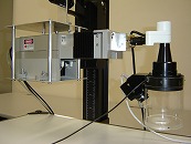
The application of laser to medical care becomes wider; the laser has been taken to dermatological treatment to remove nevi such as birth mark, angioma, etc. With right choice of the wavelength of the laser for laser treatment, the laser photothermal decomposes selectively the nevus with a lot of pigments like melanin or hemoglobin rather than normal tissue. However, the laser for treatment always has dual issues of; not causing destruction of the normal tissue remarkably by thermal diffusivity and destroying the nevus. We found well-focused fine beam of the laser would help these issues be resolved, and we are developing the therapeutic apparatus by this new viewpoint. This optical apparatus in which the laser scanning lenses are fitting into the lens barrel by the shrink fitter can well-focus fine laser beam over a wide scanning width.
Research of high frequency and 671nm laser therapy apparatus
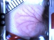
In this research, the tattoo likened to birthmark and lentigo is given to the rat skin, and the laser irradiation experiment is conducted to the tattoo. It is thought that the apparatus that can be treated to skinning deep can be developed by using the laser of wavelength 671 nm. Moreover, shortening the treatment time becomes possible by using the high frequency laser.
Research of High Frequency and Spot Diameter 30 micro meter Laser Therapy Apparatus
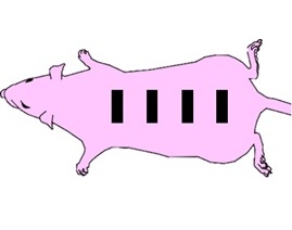
In this research, the tattoo likened to birthmark and lentigo is given to the rat skin, and the laser irradiation experiment is conducted to the tattoo. It is thought that the new apparatus is treatable to the skin deep part by using a laser of wavelength 1,064nm. Moreover, shortening the treatment time becomes possible by using the high frequency laser.
Research of high frequency and 671nm laser therapy apparatus
In this research, the tattoo likened to birthmark and lentigo is given to the rat skin, and the laser irradiation experiment is conducted to the tattoo. It is thought that the apparatus that can be treated to skinning deep can be developed by using the laser of wavelength 671 nm. Moreover, shortening the treatment time becomes possible by using the high frequency laser.
Estimation of Friction Characteristics of Aneurysm Clips
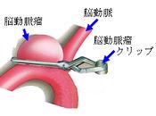
A cerebral aneurysm is the dilation,bulging, or ballooning out of part of the wall of a vein or artery in the brain. If the cerebral aneurysm ruptures, it will become serious life-threatening condition. An aneurysm clip -sugita clip- is a medical instrumentation that is used in operation of the cerebral aneurysm to clip the ruptured aneurysm and to reduce the risk of rebleeding. In order to prevent the sugita clips from slipping out of the blood vessels, a number of pyramidal depressions are formed on their clamp surfaces. However, it is not examined whether there is more suitable shape to prevent slipping other than the pyramid shape. In this research, we used a THG laser process machine to produce the clamp surface with dimples or grooves. Frictional characteristics of each clamp surface was examined.